TOKYO, Jan 24, 2020 - (JCN Newswire) - NEC Corporation (TSE: 6701), a leader in the integration of IT and network technologies, today announced the development of millimeter-wave(1) distributed antennas for the efficient use of 5G millimeter-wave spectrum (28GHz band) for the first time. Demonstration experiments were conducted with this technology at the NEC Tamagawa Plant in 2019, where the capability of high-speed, large-capacity communications with stable propagation channel quality was confirmed.

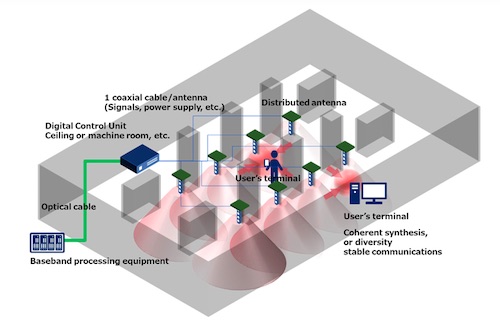
Figure 1: Conceptual diagram of a millimeter-wave distributed antenna in a building

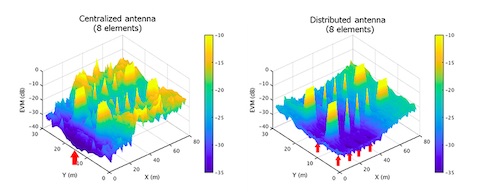
Figure 2: Communication quality simulating an office(4) (Red arrows indicate the antenna position, blue indicates high communication quality, and yellow indicates the portion of deterioration caused by shielding or interference)
In terms of background, 5G uses millimeter waves, which have frequency bands more than 10 times higher than 4G, and are expected to contribute to a wide range of services that provide high-speed, large-capacity, low-latency, and multiple connections. Due to the nature of millimeter waves, however, communication quality is susceptible to deterioration due to shielding and interference caused by obstacles and installations. As a result, it is necessary to establish a large number of base stations to ensure communication quality. However, in places with limited space, such as homes and workplaces, there is also a need to downsize base stations.
To resolve these challenges, NEC developed digital coordination technologies to connect distributed antenna elements for wireless satellite stations (RU: Radio Unit) of 5G millimeter-wave (28GHz-band) base stations. Moreover, NEC resolved the issues of shielding and diffraction of propagation paths for interior mobile communications using millimeter-wave communication. This technology applies NEC's proprietary massive MIMO(2), which combines a large number of independent antennas, in order to deliver millimeter-wave high-speed, high-capacity communications with stable communication quality.
In addition, by connecting distributed antennas to control units using a frequency multiplexer that consolidates multiple signals, NEC resolved issues related to attenuation, synchronization and power supply that might arise when connecting antennas and control units with high-frequency cable or optical cable, thereby helping to facilitate the installation of antennas. Furthermore, NEC has produced smaller antennas (approximately 5cmx2cm with 8 components) by designing and implementing circuits cultivated through NEC's iPASOLINK microwave communication system.
NEC's demonstration experiment consisted of a system with eight antennas, a control unit for controlling antennas, and a baseband processing unit that controls antennas.
In the experiment, NEC applied digital beamforming(3), which had been developed in the sub-6GHz and millimeter bands, to 28GHz band antennas. By combining and multiplying the space of radio waves, NEC achieved not only high-speed, high-capacity communication, but also stabilized the propagation path. NEC also achieved stable communications in difficult propagation environments, such as shadowing by walls, interference from reflective waves, and environments where multiple terminals are closely linked.
Going forward, NEC will continue to conduct demonstration tests in various environments, such as office buildings, commercial facilities, and factories, with the aim of commercializing this technology by the end of 2020.
NEC will announce details of a feasibility study on this technology at IEEE Radio Wireless Week 2020 held in San Antonio, Texas, USA, from January 26 to 29. NEC will also exhibit this technology at a MWC Barcelona 2020 in Barcelona, Spain, from February 24 to 27.
Under NEC's Mid-term Management Plan 2020, which covers the three-year period to FY2020, NEC is promoting service businesses in new areas that leverage the strengths of its network technologies. Through these developments, NEC will accelerate the provision of "NEC Smart Connectivity"(5) utilizing network flexibly to dynamically link data produced by people and goods across industries, and to create new social value.
(1) Millimeter-wave
Compared to sub-6GHz, challenges at the millimeter-wave level include large attenuation per distance and attenuation by shielding due to shorter wave length, divergence difficulty, and the large influence of reflection and intervention.
(2) Massive MIMO
This is an enhancement of Multiple Input Multiple Output that utilizes the flexibility of many independent transceivers to simultaneously improve spatial multiplexing and the quality stability of radio channels.
Reference:
NEC develops compact and lightweight massive-element active antenna system for 5G communications, https://bit.ly/38xHtCS
NEC succeeds in simultaneous digital beamforming that supports 28 GHz band for 5G communications, https://bit.ly/38ADC80
(3) Digital beamforming
A technology that focuses on a particular direction by spatially combining and multiplying radio waves. This reduces radio interference between the base station and the terminal, thereby providing a more stable radio wave.
(4) Simulation using an index (EVM: Error Vector Magnitude) to measure the quality of digital-modified signals.
Reference:
Definition of EVMs (3GPP Standard), https://bit.ly/2Rp5JBA
(5) NEC Smart Connectivity
Network services that draw on NEC's accumulated expertise and track record in network technologies and related solutions. https://bit.ly/2TRXNKt
About NEC Corporation
NEC Corporation is a leader in the integration of IT and network technologies that benefit businesses and people around the world. The NEC Group globally provides "Solutions for Society" that promote the safety, security, efficiency, and equality of society. Under the company's corporate message of "Orchestrating a brighter world," NEC aims to help solve a wide range of challenging issues and to create new social value for the changing world of tomorrow. For more information, visit NEC at https://www.nec.com.

Figure 1: Conceptual diagram of a millimeter-wave distributed antenna in a building

Figure 2: Communication quality simulating an office(4) (Red arrows indicate the antenna position, blue indicates high communication quality, and yellow indicates the portion of deterioration caused by shielding or interference)
Copyright 2020 JCN Newswire. All rights reserved. www.jcnnewswire.com
